Stray Voltage from Stray Currents
Stray Voltage, like Mold, is a side effect of another instigator. Whereas for Mold the primary instigator is Moisture, for Stray Voltage it is "Stray Current". Stray Current, however, is not "Stray" per se, as it is a natural result and occurrence of things as built. Where it comes into play is where it provides avenues of irritation or shock that should not exist, but do. It is both a Utility AND User owned and produced ailment. Herein then, is the basis for why it occurs, from a basic construct to the contemporary electrical setting.
When a Source of power is connected to a Load, a current flows producing some effect: heating, ventilations, lighting, etc. When the Source and the Load are close by, the situation is simply as shown below.

When the Source and the Load are a few miles or more apart, the very low resistance of the wire becomes significant. That is because the Wire Resistance will cause a voltage to be developed over the length of the wire that will reduce the voltage available to the load, as shown below. That is the reason we do not have a DC distribution system.

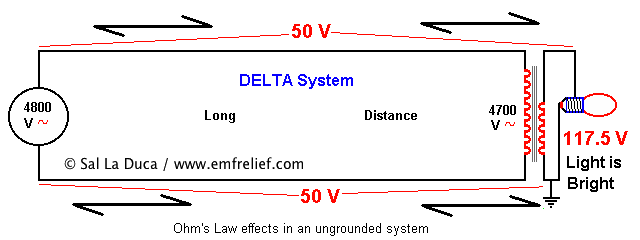
With AC the wire resistance problem can almost be eliminated because the power is sent at high voltages (with a corresponding lower current for the same power, and a simultaneous reduction in the voltage drop over the long wire distance) and stepped down to the required voltage, through a transformer, at the point of use. So if the power is sent at 4800 volts, even a 100-volt reduction will seem small when the voltage is stepped down to 120/240, keeping it within reasonable and expected limits. This is particular to the Delta distribution system, as shown below.
Another distribution system (WYE, as shown below) employs a wire as a "ground" reference. It is connected to the Earth at many points along the path of travel from Source to Load. Although in the previous examples it was simply shown that a voltage was developed along each leg of the circuit, reducing that available from the source, in a WYE system a counterintuitive process occurs. That is, at the source one leg of the circuit is connected to ground and is ideally at zero volts, so that at a distance a voltage is produced on the grounded wire that adds to zero, producing a voltage increase above zero, while the energized leg develops a voltage drop that reduces the available source voltage. The concept is the same as in the other examples, except that now there is a (zero volts) ground reference point to deal with. In this type of system, although the wire resistance comes into play in a limited fashion (because of the reduced currents due to the use of high voltage), it is not uncommon to find the "ground" reference to be at 5-15 volts above the Earth's potential* (even though there are many ground rods in contact with the soil (a generally poor electrical conductor)). In the diagram below, the complexity increases significantly because of the redundant current paths on the Neutral/Ground wire due to the interconnection to Public Water Main Systems (while some may think that current will flow through "the" path of least resistance, in fact it will flow through all available paths, with the amount of flow affected by the individual electrical resistance). This serves to reduce the overall voltage drop produced in that leg of the circuit. However, the voltage may still be high enough to produce a shock in creatures in electrical contact with the Earth. A break in any one of the redundant Neutral Paths will produce an increase in voltage drop from Source to Load (due to an increase in the overall equivalent resistance), and a corresponding elevation of the voltage at the ground rod at the point of use, even though the rod is stuck 8-10 feet into the soil!
* While this statement may be straightforward, measuring it is not always as simple as it sounds if the tester (tinkerer or electrician) has not had previous experience. To measure Stray Voltage between an electrical system ground and the soil, insert another metal onject in the soil five (5) to ten (10) feet away from the electrical system ground (ideally this other ground should be inserted at least 12 inches into the soil to ensure a good electrical contact). Then measure for AC Voltage between the two pieces of metal. The isolated one should be at zero because it has no current flow, while the electrical system ground will be at something other than zero because it's part of a long electrical circuit.

Thus far, the above contributions are related to the utility alone. The customer's contributions are outlined below.
The common residential wiring system is comprised of three wires providing 120 and 240 V, as shown below.
The sketch is simplified for clarity.

This system works well and is time tested. However, as with all mechanical systems, it requires maintenance. But that is not what the typical homeowner is equipped for. So connections become frayed and loose due to oxidations over many years, especially due to the use of Aluminum wire. When the middle-wire (Neutral / Ground) connection behind the meter becomes loose, it can present voltages within a single residence that are a fire hazard, as shown below.

The solutions to this dilemma were to either educate the consumer, or make amendments to how things were wired (the path of least resistance). As this latter path was chosen, metallic water piping came into play to provide a voltage stability solution, by providing an alternate path for current flow, that really belonged on the middle wire (Neutral Current), as shown above.
When that Neutral Current flows through metallic water piping it becomes an electrocution hazard to the weekend plumber, and a source of Stray Current that is shared by Several or Many neighbors, depending on the integrity and construction of the distribution system, as shown below.

In addition to the above, even if everything is wired properly, there may be occasion to find Elevated Voltage levels at the residential Grounding Point (relative to Earth ground) due to currents on the Neutral wire. These currents, being several orders of magnitude greater than Primary Currents, will develop a voltage across the run of wire from the Distribution panel and Grounding Point to the Source transformer (as shown below). Again, in such instances a dog, cow, or other creature in electrical contact with the earth will be shocked when it touches anything connected to the electrical system "ground" such as a water spicket, a ground rod, etc.. A human will experience the same if walking barefoot.

The Neutral current can be reduced by Statically Balancing the loads (attaching circuits to different sources) such that most of the current travels on the energized wires. However, it can never be totally eliminated (as shown below) because it's not possible to predict what will be energized when, and Dynamic Balancing does not exist.

Some related problems, because of the requirement to interconnect Cable and Telephone Grounds to the Electrical Ground, ensue because of duplicate paths for the return (Neutral) current to flow (as shown below). Even a few volts of difference between the Earth Ground and the Electrical System Ground is sufficient to drive significant currents through the Cable shield causing TV interference, and through the Telephone ground causing an AC voltage presence on the associated wiring due to Induction.

One way to identify the presence of Stray Currents (and resultant Stray Voltage) is with a cheap Gaussmeter ($45+/-), as any uncancelled current path (Net Current / Stray Current) will exhibit a wide-ranging Magnetic Field. This picture get muddled, however, when common wiring errors occur, causing a Magnetic Field presence that can engulf the entire residence. Another is by using an AC Voltmeter that can read milliVolts and has a 10 Megaohm input impedance. Cheaper meters have a lower input impedance and significantly reduce the ability to detect signals.
While "experts" and "authorities" have tried to define a voltage level above which action should be taken, that level may still be too high for certain individuals or animals. The relevance can vary based on the age and health of the affected individual or animal, among other things. As in all irritants, the end goal is to try to achieve levels that are As Low As Reasonably Achievable (ALARA). "Reasonably" however, can be defined differently by different parties, primarily based on how much money and effort are required to reach ALARA, which is where the finger-pointing and litigation occur. Nevertheless, below are practical steps to approach that ALARA.
Some of the possible recourses for Residential-Generated "Stray Voltage" are:
1) Increase the wire size to the Source (especially the Neutral), reducing its resistance.
2) Provide a better balancing of loads between energized buses (to reduce Neutral Current).
3) Reduce the number of sources fed from 120V, and increase those fed from 240V(to reduce Neutral Current).
4) Bring the Source Transformer closer to the point of use (to reduce Neutral wire resistance by reducing its length).
5) Periodically inspect ALL connections for snugness and integrity (especially the Neutral).
6) Eliminate the use of the interconnected Metallic Water Piping as a "shared" Grounding Point, yet retain local grounding for lightning protection.
While these may appear simplistic, there are specific additional details that need to be observed for each alternative, to ensure a safe application.
Some of the possible recourses for Utility-Generated "Stray Voltage" are:
1) Increase the size of the Primary Neutral wire, reducing its resistance.
2) Provide a better balancing of loads between phases (to reduce Neutral Current).
3) Provide regular changes between WYE and DELTA feeds to customers along a circuit (to eliminate long spans of redundant current paths).
4) Provide Non-Conductive breaks in the Public water main at regular intervals.
5) Periodically inspect ALL connections for signs of deterioration (especially the Neutral), using Infrared photography under heavy load conditions. Repair as necessary.
6) Perform regular and frequent Magnetic and Voltage surveys to identify problems before they become troublesome.
7) When the voltage difference between the Electrical System Ground and any other point in the soil (say as little as 10 feet away) is excessive, request Neutral Isolation from the local utility. You be the judge as to what is excessive. This author sees that voltage difference regularly around 1/2 Volt (500 mV), but has seen it as high as 25 Volts. Sensitive people (children, the elderly, the sick, etc.) can sense very low values and be irritated by it.
Again, while these may appear simplistic, there are specific additional details that need to be observed for each alternative, to ensure a safe application.
Values shown herein are for illustrative purposes only, and do not necessarily reflect all variants of real-life application. Additionally, Primary systems are comprised of 3 phases, whereas only one phase is shown within this document. This brief is not meant to be exhaustive or all-inclusive, and real-life remedies are bound to comprise components of each category.
Disclaimer: Electrical systems are by their very nature dangerous and, if certain precautions are not followed when testing, maybe even fatal. Please, please, if you have any uncertainty in what you wish to do, hire someone that is competent. If there is any question of unfamiliarity with someone who is supposed to know what to do and doesn't, print this page and have them read and understand it before proceeding. The author cannot be held liable for failure to follow proper technical precautions.
-------------------------------------------
Full text and graphics © 2009
Environmental Assay Inc. /
Sal La Duca ,
Sal La Duca
Indoor Environmental Specialist
BS, BBEC/BBEI, CIEC
FCC Licensed
792 Green St.
Phillipsburg NJ 08865 USA
908-454-3965
'[참고 자료] > Stray voltage' 카테고리의 다른 글
| STRAY VOLTAGE DETECTOR (0) | 2009.07.31 |
|---|---|
| Stray Voltage Test Procedure for Electrical Contractors (2007.11) (0) | 2009.07.31 |
| Con Ed Finds 1,214 Stray Voltage Sites in One Year (0) | 2009.07.31 |
| Farm Customers — Stray Voltage (0) | 2009.07.31 |
| What Causes Stray Voltage ? (0) | 2009.07.31 |